(Obsolete) Saftronics VG10 – Dynamic Torque Vector AC Drive
(Obsolete FINCOR Series 6600)
- Saftronics VG10 – Dynamic Torque Vector AC Drives
- Pricing, Dimensions & Weights
- Optional DC Link Reactors
- Options & Accessories
- Palm Pilot Saflink Kit
- Relay Output Card
- SR10 Radio Modem Kit
- Digital I/O Interface Card
- Analog I/O Interface Card
- SF-10 Ethernet Module
- PGX Encoder Feedback Card
- Encoder + Analog Output Card
- PG Feedback Card (VG10 only)
- PG Feedback Card (VG10 only)
- Synchronized Operation Card (VG10 only)
- 24 VDC or 24/120 VAC Interface Card Kit (PC10, GP10 or VG10 Inverter)
- Air Pressure Sensor + V/I Converter Output Card
- SDBU – Dynamic Brake Module
- Ratings Efficiency & Watts Loss (230, 460VAC)
- Standard Specifications
- For Drive Dimension Sheets, contact Joliet Technologies
- Basic Connection Diagrams
- For Spare Parts, contact Joliet Technologies
Standard Specifications
| Environmental Conditions | |||
|
|
|||
| Enclosure | NEMA 1 Standard (NEMA 12, Open Chassis) | ||
|
|
|||
| Installation Location: | NEMA 1 | Intended for indoor use only, less than 1000 meters (3300 feet) elevation, not in contact with corrosive gas, oil mist, dust or direct sunlight. | |
| NEMA 4 | Intended for use indoors to protect the enclosed equipment against splashing water, seepage of water, falling or hose directed water and severe external condensation. Installation should be less than 1000 meters (3300 feet) elevation, not in contact with corrosive gas, oil mist or direct sunlight. | ||
| NEMA 12 | Intended for indoor use only, less than 1000 meters (3300 feet) elevation, not in contact with corrosive gas, oil mist, dust or direct sunlight. |
||
|
|
|||
| Stored Temperature | -25 to + 65°C (-13° to + 149°F) | ||
|
|
|||
| Ambient Temperature | -10 to 50°C (+14 to 122°F) Ventilating covers must be removed under conditions exceeding +40°C (+104°F) for models rated at 30 Hp or less. | ||
|
|
|||
| Humidity | 5% to 95% relative humidity (non-condensing). | ||
|
|
|||
| Vibration | 3mm peak from 2-9 Hz, 9.8 m/s2 from 9-20 Hz, 2 m/s2 from 20-55 Hz, 2 m/s2 from 55-200 Hz. | ||
|
|
|||
| Cooling Method | 1 Hp and below – Convection Above 1 Hp – Fan-cooled |
||
|
|
|||
| Output | |||
|
|
|||
| Rated Output Voltage | 230 VAG, 3-Phase, 200V/50 Hz or 3-Phase, 200V, 220V, 230V/60 Hz 460 VAG, 3-Phase, 380V, 400V, 415V, 440V/50 Hz or 3-Phase 380V, 400V, 440V, 480V/60 Hz |
||
|
|
|||
| Rated Frequency | 50/60Hz | ||
|
|
|||
| Overload Current Rating | 150% of rated current for 1 min. 180% of rated current for 0.5 sec > 30 Hp 200% of rated current for 0.5 sec < or = 30 Hp |
||
|
|
|||
| Power Supply | |||
|
|
|||
| Rated Input AC Voltage | 230 VAG: 200 to 230 VAG 50/60 Hz, 3 phase (1/4 to 30 Hp) 230 VAG: 200 to 220 VAC/50 Hz, 200 to 230 VAC/60 Hz 3 phase (40 Hp or more) 460 VAG: 380 to 480 VAG 50/60 Hz, 3 phase (1/2 to 30 Hp) 460 VAG: 380 to 440 VAC/50 Hz, 3 phase, 380 to 480 VAC/60 Hz (40 Hp or more) Voltage: +10%, -15%; Voltage Unbalance – Within 3% Frequency: +/-5% |
||
|
|
|||
| Control System | Sinusoidal PWM Control (V/Hz control, Dynamic Torque Vector Control, Flux Vector Control with Optional Encoder Card) | ||
|
|
|||
| Momentary Voltage Dip | 230 VAG: When the input voltage is 165 VAG or more, the drive can be operated continuously. 460 VAG: When the input voltage is 310 VAG or more, the drive can be operated continuously. When the input voltage drops below 165/310 VAG from rated voltage, the drive can be operated for 15ms. The smooth recovery method is selectable. |
||
|
|
|||
| Control | |||
|
|
|||
| Starting Torque selected | 200%, 30 Hp or less, 180%, 40 Hp or more with Dynamic Torque Control | ||
|
|
|||
| Carrier Frequency | 0.75-15 kHz -75 Hp or less 0.75-10 kHz -100 Hp or more |
||
|
|
|||
| Frequency Setting Resolution | Analog: 1/3000 of max. frequency (0.02 Hz/60 Hz; 0.05 Hz/150 Hz) Digital: 0.01 Hz (max. frequency up to 99.99 Hz); 0.1 Hz (max. frequency of 100 Hz or more) |
||
|
|
|||
| Output Frequency Accuracy (Stability) | Analog setting: :to.2% or less of max. frequency (@ 25:t 10°G) Digital setting: :to.01 % or less of max. frequency (@ -10 to +50°G) |
||
|
|
|||
| Voltage/Frequency Characteristics 01 /F) | Output voltage at base frequency can be adjusted separately, such as 80 to 240 V (230V series) or 320 to 480V (460V series) | ||
|
|
|||
| Torque Boost | Auto: 0.0 setting for optimum control corresponding to the load torque Manual: 0.1 to 20.0 code setting for constant/variable torque load |
||
|
|
|||
| Accel eration/Decel eration | 0.01 to 3600 seconds (Four acceleration/deceleration time settings are possible Characteristics independent of each other by selecting digital input signals | ||
|
|
|||
| Operating Sound Selection | The drive carrier frequency can be changed to reduce audible noise and sound tone. | ||
|
|
|||
| Analog/Pulse Output | Scale calibration of externally connected analog meter (10 VDC, 0-200% gain setting) and pulse output (300 to 6,000 P/S) | ||
|
|
|||
| Data Protection | Data lock is possible to ensure that the data codes are not changed. | ||
|
|
|||
| Pattern Operation | Six independent stages (frequency up to 400 Hz, duration up to 6,000 seconds each). Configuration: Single cycle Repeating cycling Single cycle with continuous last setting speed |
||
|
|
|||
| Momentary Power Loss Ride Thru | Six selections available. (Refer to Power Supply Specification.) | ||
|
|
|||
| High/Low Limiter | Output frequency upper and lower range limit 0 to 400 Hz; 1 Hz step settings. | ||
|
|
|||
| Bias | Magnitude of the zero offset can be set from -400 to 400 Hz (0.1 Hz steps.) | ||
|
|
|||
| Gain | Output frequency gain corresponding to the reference signal can be set from 0 to 200% (0.1 % steps.) | ||
|
|
|||
| Programmable Jump Frequency | Three selectable frequencies can be set to avoid a mechanical resonant point. Width is adjustable from 0 to 30 Hz (1 Hz steps.) | ||
|
|
|||
| Slip Compensation Control | Maintains motor at constant speed with load fluctuations. Adjustable from 0.00 Hz to 15.00 Hz. | ||
|
|
|||
| Torque Limit Control | Output torque can be controlled within a range of 20% to 200% (1 % steps.) | ||
|
|
|||
| 15 Step Preset Speed | 15 programmable preset speeds selectable by 4 contact closures. | ||
|
|
|||
| PID | Normal or Inverse operation can be selected. | ||
|
|
|||
| Momentary or Maintained Contact Operation | Selection between the maintained contact operation/stop command (2-wire operation) or the momentary contact (3-wire operation). | ||
|
|
|||
| Terminal Function Change | Multi-Use terminals changed via Function Code settings. X1 to X9 inputs; Y1 to Y 4 transistor output and Y5 relay output. | ||
|
|
|||
| Line to Drive Transition Logic | Provides the logic for transferring a motor from AC line to drive operation in a bypass system. | ||
|
|
|||
| Sensorless Vector Control (Dynamic Torque Vector Control) | Improves torque characteristics throughout the speed range. Improves speed regulation. |
||
|
|
|||
| Operation | |||
|
|
|||
| Frequency Reference Signal | Speed potentiometer: 0 to +10 VDC, 10 to 0 VDC 4 to 20 mA, 20 to 4mA 0 to +10 VDC |
||
|
|
|||
| Digital Input Signals | Multi-step frequency selection (1 to 15 steps) Acceleration and deceleration time selection (3 steps) Self-Hold selection (HLD) Coast-to-Stop command (BX) Alarm Reset (RST) External Alarm (THR) Jogging (JOG) Frequency setting 2 / Frequency setting 1 (Hz2 / Hz1) Motor 2 / Motor 1 (M2/ M1) DC injection brake command (DCBRK) Torque limit 2 / Torque limit 1 (TL2 / TL 1) Switching operation from line to drive (50 Hz) (SW50) Switching operation from line to drive (60 Hz) (SW60) UP command (UP) DOWN command (DOWN) Edit permission command (data change permission) (WE-KP) PID control cancellation (Hz/PID) Normal/inverse switching (Terminals 12 and C1) (IVS) Interlock (52-2) (lL) Torque control cancellation (Hz/TRQ) Link operation selection (Standard: RS485, Option: BUS) (LE) Universal 01 (U-DI) Pick up start mode (STM) SY-PG enable (PG/Hz) Zero speed command (ZERO) Timed alarm stop command (STOP 1) Timed alarm stop command with Deceleration time 4 (STOP 4) Pre-exiting command (EXITE) |
||
|
|
|||
| Digital Output Signals | One Dry, Form C “fault” output contact rated 250 VAG, 0.3 amp. One auxiliary relay contact rated 250 VAG, 0.3 amp Four Open collector outputs each rated 27 VDC, 50 mA from external power. One relay and four open collector outputs can be configured to provide one of the following functions:
|
||
|
|
|||
| Protective Functions |
|
|
|
|
|
|||
| Keypad Features | Digital Display – 4 digit LED Six Languages (English, German, French, Spanish, Italian, Japanese) Graphic Display – LCD, with backlight Nine program menu includes data copy function |
||
|
|
|||
| Keypad Display |
|
||
|
|
|||
| Keypad Display in Program Mode Function Code and setting data displayed (see Operation Panel paragraph) | |||
|
|
|||
| RS485 RTU Serial Communication | – Physical Level: | EINRS485 | |
| – Transmission Distance: | 500m max. | ||
| – Number of nodes: | 32 total | ||
| – Transmission Speed: | 19200, 9600, 4800, 2400 (bits/s) | ||
| – Transmission mode: | Half duplex | ||
| – Transmission protocol: | Modbus RTU | ||
| – Character code: | Binary | ||
| – Character length: | 8 bits | ||
| – Error check: | CRC | ||
|
|
|||
| Charge Lamp (LED) | Lights when DC Link capacitor voltage is present. | ||
|
|
|||
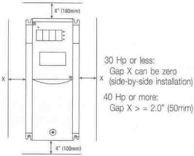
| Mounting Clearance | |||
Prices and specifications subject to change without notice.
To purchase any Saftronics drives or information, contact us at:
Phone (815) 725-9696,
Toll Free (866) 492-9888,
Fax (815) 725-9393 or
E-mail info@joliettech.com