 Guide to Harmonics
with AC Variable Frequency Drives
Contents
- Introduction
- Basics of the harmonics phenomena
- Harmonic distortion sources and effects
- Harmonic distortion calculation by using DriveSize software
- Circuit diagram for the calculation example
- Input data for motor load
- Motor selection
- Inverter selection
- Inverter supply unit data
- Network and Transformer data input
- Calculated harmonic current and voltage
- Calculated harmonic currents in graphical form
- Part of the printed report
- Standards for harmonic limits
- EN61800-3 (IEC1800-3) Adjustable speed electrical power drive systems
- IEC1000-2-2, Electromagnetic compatibility (EMC)
- IEC1000-2-4, Electromagnetic compatibility (EMC)
- IEC1000-3-2, Electromagnetic compatibility (EMC)
- IEC1000-3-4, Electromagnetic compatibility (EMC)
- IEEE519, IEEE Recommended practices and requirements for harmonic control in electrical power systems
- Evaluating harmonics
- How to reduce harmonics by structural modifications in the AC drive system
- Factors in the AC drive having an effect on harmonics
- Table: List of the different factors and their effects
- Using 6-pulse diode rectifier
- Using 12-pulse or 24-pulse diode rectifier
- Using phase controlled thyristor rectifier
- Using IGBT bridge
- Using larger DC or AC inductor
- Other methods for harmonics reduction
- Tuned single arm passive filter
- Tuned multiple arm passive filter
- External active filter
- Summary of harmonics attenuation
- 6-pulse rectifier without inductor
- 6-pulse rectifier with inductor
- 12-pulse rectifier with polygon transformer
- 12-pulse with double wound transformer
- 24-pulse rectifier
- Active IGBT rectifier
- Definitions
Other methods for harmonics reduction
Filtering is a method to reduce harmonics in an industrial plant when the harmonic distortion has been gradually increased or as a total solution in a new plant. There are two basic methods: passive and active filters.
Tuned single arm passive filter
The principle of a tuned arm passive filter is shown in Figure 8.1. A tuned arm passive filter should be applied at the single lowest harmonic component where there is significant harmonic generation in the system. For systems that mostly supply an industrial load this would probably be the fifth harmonic. Above the tuned frequency the harmonics are absorbed but below that frequency they may be amplified.
- Detuned – Single tuning frequency
- Above tuned frequency harmonics absorbed
- Below tuned frequency harmonics may be amplified
- Harmonic reduction limited by possible over compensation at the supply frequency and network itself
Figure 8.1 Tuned single arm passive filter.
This kind of filter consists of an inductor in series with a capacitor bank and the best location for the passive filter is close to the harmonic generating loads. This solution is not normally used for new installations.
Tuned multiple arm passive filter
The principle of this filter is shown in Figure 8.2. This filter has several arms tuned to two or more of the harmonic components which should be the lowest significant harmonic frequencies in the system. The multiple filter has better harmonic absorption than the one arm system.
- Capacitive below tuned frequency/Inductive above
- Better harmonic absorption
- Design consideration to amplification harmonics by filter
- Limited by KVAr and network
Figure 8.2 Tuned multiple arm passive filter.
The multiple arm passive filters are often used for large DC drive installations where a dedicated transformer is supplying the whole installation.
External active filter
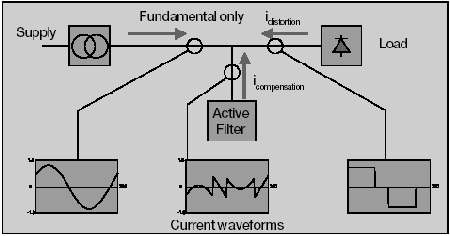
A passive tuned filter introduces new resonances that can cause additional harmonic problems. New power electronics technologies are resulting in products that can control harmonic distortion with active control. These active filters, see Figure 8.3, provide compensation for harmonic components on the utility system based on existing harmonic generation at any given moment in time.

Figure 8.3 External active filter principle diagram.
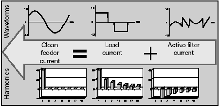
The active filter compensates the harmonics generated by nonlinear loads by generating the same harmonic components in opposite phase as shown in Figure 8.4. External active filters are most suited to multiple small drives. They are relatively expensive compared to other methods.

Figure 8.4 External active filter waveforms and harmonics.


 Guide to Harmonics
