 Guide to Harmonics
with AC Variable Frequency Drives
Contents
- Introduction
- Basics of the harmonics phenomena
- Harmonic distortion sources and effects
- Harmonic distortion calculation by using DriveSize software
- Circuit diagram for the calculation example
- Input data for motor load
- Motor selection
- Inverter selection
- Inverter supply unit data
- Network and Transformer data input
- Calculated harmonic current and voltage
- Calculated harmonic currents in graphical form
- Part of the printed report
- Standards for harmonic limits
- EN61800-3 (IEC1800-3) Adjustable speed electrical power drive systems
- IEC1000-2-2, Electromagnetic compatibility (EMC)
- IEC1000-2-4, Electromagnetic compatibility (EMC)
- IEC1000-3-2, Electromagnetic compatibility (EMC)
- IEC1000-3-4, Electromagnetic compatibility (EMC)
- IEEE519, IEEE Recommended practices and requirements for harmonic control in electrical power systems
- Evaluating harmonics
- How to reduce harmonics by structural modifications in the AC drive system
- Factors in the AC drive having an effect on harmonics
- Table: List of the different factors and their effects
- Using 6-pulse diode rectifier
- Using 12-pulse or 24-pulse diode rectifier
- Using phase controlled thyristor rectifier
- Using IGBT bridge
- Using larger DC or AC inductor
- Other methods for harmonics reduction
- Tuned single arm passive filter
- Tuned multiple arm passive filter
- External active filter
- Summary of harmonics attenuation
- 6-pulse rectifier without inductor
- 6-pulse rectifier with inductor
- 12-pulse rectifier with polygon transformer
- 12-pulse with double wound transformer
- 24-pulse rectifier
- Active IGBT rectifier
- Definitions
Evaluating harmonics
The “Guide for Applying Harmonic Limits on Power Systems” P519A/D6 Jan 1999 introduces some general rules for evaluating harmonic limits at an industrial facility. The procedure is shown in the flowchart in Figure 6.1.

Figure 6.1 Evaluation of harmonic distortion.
How to reduce harmonics by structural modifications in the AC drive system
Harmonics reduction can be done either by structural modifications in the drive system or by using external filtering. The structural modifications can be to strengthen the supply, to use 12 or more pulse drive, to use a controlled rectifier or to improve the internal filtering in the drive.
Factors in the AC drive having an effect on harmonics
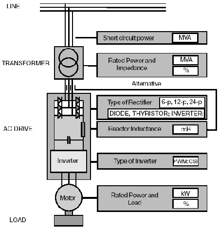
Figure 7.1 shows the factors in the AC drive system which have some influence on harmonics. The current harmonics depend on the drive construction and the voltage harmonics are the current harmonics multiplied by the supply impedances.

Figure 7.1 Drive system features affecting harmonics.
Table: List of the different factors and their effects
| The cause | The effect |
| The larger the motor… | the higher the current harmonics |
| The higher the motor load… | the higher the current harmonics |
| The larger the DC or AC inductance… | the lower the current harmonics |
| The higher the number of pulses in the rectifier… | the lower the current harmonics |
| The larger the transformer… | the lower the voltage harmonics |
| The lower the transformer impedance… | the lower the voltage harmonics |
| The higher the short circuit capacity of supply… | the lower the voltage harmonics |
Using 6-pulse diode rectifier
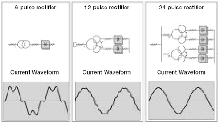
The connections for different rectifier solutions are shown in Figure 7.2. The most common rectifier circuit in 3-phase AC drives is a 6-pulse diode bridge. It consists of six uncontrollable rectifiers or diodes and an inductor, which together with a DC-capacitor forms a low-pass filter for smoothing the DCcurrent. The inductor can be on the DC- or AC-side or it can be left totally out. The 6-pulse rectifier is simple and cheap but it generates a high amount of low order harmonics 5th, 7th, 11th especially with small smoothing inductance.
The current form is shown in Figure 7.2. If the major part of the load consists of converters with a 6-pulse rectifier, the supply transformer needs to be oversized and meeting the requirements in standards may be difficult. Often some harmonics filtering is needed.

Figure 7.2 Harmonics in line current with different rectifier constructions.
Using 12-pulse or 24- pulse diode rectifier
The 12-pulse rectifier is formed by connecting two 6-pulse rectifiers in parallel to feed a common DC-bus. The input to the rectifiers is provided with one three-winding transformer. The transformer secondaries are in 30o phase shift. The benefit with this arrangement is that in the supply side some of the harmonics are in opposite phase and thus eliminated. In theory the harmonic component with the lowest frequency seen at the primary of the transformer is the 11th.
The major drawbacks are special transformers and a higher cost than with the 6-pulse rectifier.
The principle of the 24-pulse rectifier is also shown in Figure 7.2. It has two 12-pulse rectifiers in parallel with two threewinding transformers having 15o phase shift. The benefit is that practically all low frequency harmonics are eliminated but the drawback is the high cost. In the case of a high power single drive or large multidrive installation a 24-pulse system may be the most economical solution with lowest harmonic distortion.

Figure 7.3 Harmonic components with different rectifiers.
Using phase controlled thyristor rectifier
A phase controlled rectifier is accomplished by replacing the diodes in a 6-pulse rectifier with thyristors. Since a thyristor needs a triggering pulse for transition from nonconducting to conducting state, the phase angle at which the thyristor starts to conduct can be delayed. By delaying the firing angle over 90o, the DC-bus voltage goes negative. This allows regenerative flow of power from the DC-bus back to the power supply.
Standard DC-bus and inverter configurations do not allow polarity change of the DC-voltage and it is more common to connect another thyristor bridge anti-parallel with the first one to allow the current polarity reversal. In this configuration the first bridge conducts in rectifying mode and the other in regenerating mode.
The current waveforms of phase controlled rectifiers are similar to those of the 6-pulse diode rectifier, but since they draw power with an alternating displacement power factor, the total power factor with partial load is quite poor. The poor power factor causes high apparent current and the absolute harmonic currents are higher than those with a diode rectifier.
In addition to these problems, phase-controlled converters cause commutation notches in the utility voltage waveform. The angular position of the notches varies along with the firing angle.
| Supply type | Current TDH (%) | Voltage TDH (%) RSC=20 | Voltage TDH (%) RSC=100 | Current Waveform |
| 6-pulse rectifier | 30 | 10 | 2 |  |
| 12-pulse rectifier | 10 | 6 | 1.2 |  |
| IGBT Supply Unit | 4 | 8 | 1.8 |  |
| Distortion is in % of RMS values | ||||
Figure 7.4 Distortion of different supply unit types. Values may vary case by case.
Using IGBT bridge
Introducing a rectifier bridge, made of self commutated components, brings several benefits and opportunities compared to phase commutated ones. Like a phase commutated rectifier, this hardware allows both rectification and regeneration, but it makes it possible to control the DC-voltage level and displacement power factor separately regardless of the power flow direction.
The main benefits are:
- Safe function in case of mains supply disappearance.
- High dynamics of the drive control even in the field weakening range.
- Possibility to generate reactive power.
- Nearly sinusoidal supply current with low harmonic content. Measured results for one drive is shown in Figure 7.5. When comparing with Figure 7.3 we can see a clear difference. IGBT has very low harmonics at lower frequencies, but somewhat higher at higher frequencies.
- Voltage boost capability. In case of low supply voltage the DC voltage can be boosted to keep motor voltage higher than supply voltage.
The main drawback is the high cost coming from the IGBT bridge and extra filtering needed.

Figure 7.5 Harmonics in line current IGBT line generating unit.
Using a larger DC or AC inductor
The harmonics of a voltage source AC drive can be significantly reduced by connecting a large enough inductor in its AC input or DC bus. The trend has been to reduce the size of converter while the inductor size has been also reduced, or in several cases it has been omitted totally. The effect of this can be seen from the curve forms in Figure 7.6.

Figure 7.6 The effect of the inductor on the line current.
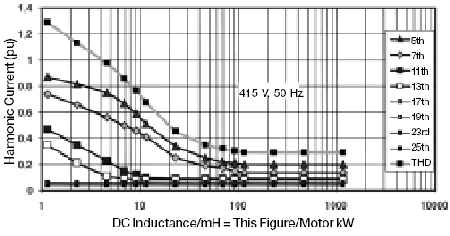
The chart in Figure 7.7 shows the effect of the size of the DC inductor on the harmonics. For the first 25 harmonic components the theoretical THD minimum is 29%. That value is practically reached when the inductance is 100 mH divided by the motor kW or 1 mH for a 100 kW motor (415 V, 50 Hz). Practically sensible is about 25 mH divided by motor kW, which gives a THD of about 45%. This is 0,25 mH for a 100 kW motor.

Figure 7.7 Harmonic current as function of DC inductance.
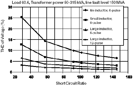
The voltage distortion with certain current distortion depends on the Short Circuit Ratio Rsc of the supply. The higher the ratio, the lower the voltage distortion. This can be seen in Figure 7.8.

Figure 7.8 THD Voltage vs Type of AC drive and transformer size.
Figure 7.9 introduces a simple nomogram for estimation of harmonic voltages. On the graph below right select first the motor kilowatt, then the transformer kVA and then move horizontally to the diagonal line where you move upwards and stop at the curve valid for your application. Then turn left to the y-axis and read the total harmonic voltage distortion.

Figure 7.9 Total harmonic distortion nomogram.
Results from laboratory tests with drive units from different manufacturers are shown in Figure 7.10. Drive A with large DC inductor has the lowest harmonic current distortion, drives with no inductor installed have the highest distortion.

Figure 7.10. Harmonic current with different DC-Inductances.


 Guide to Harmonics