Rerplacement Guide
- 230V Drive Cross Reference
- 460V Drive Cross Reference
- Options Cross Reference
- Product Differences and Remedies
Installation Procedure
- Disconnect all sources of power from the FlexPak 3000 panel.
- Label any wires that are not already marked.
- Remove all wiring connections from the FlexPak 3000 panel.
- Loosen or remove the mounting screws holding the panel to the cabinet. (Frame A, up to 60 hp, drives have three screws;
all others have six screws). Carefully remove the panel from the cabinet.
Note : The DCS800-EP panel drive is designed with the same mounting hole placement as the Reliance Electric FlexPak 3000 panel. The drive width is slightly larger but the required clearances are less, allowing the DCS800-EP to use the existing cabinet. - Temporarily secure all individual wires, cables and harnesses away from the mounting surface to avoid damage during mounting.
- Mount the DCS800-EP panel drive into the cabinet and secure the mounting screws to appropriate tightness.
- Attach the power cables to the DCS800-EP using the table and diagram on the following pages and in the installation manual.
- Attach the control wires to the DCS800-EP as discussed in the next section
| Important! Prior to start up, perform all items listed on the installation checklist from the DCS800-EP Installation and Startup Manual. |
| Important! Only qualified electricians are allowed to install and maintain the drive. Never work on the drive, motor cable or motor when main power is applied. |
| Important! Use all appropriate lifting techniques when removing or installing a drive panel. |
© Copyright 2016 ABB. All rights reserved.
Specifications subject to change without notice.
DCS800-EP | Reliance FlexPak 3000 Replacement
![]()
Wiring and Configuration
Wiring and configuration changed after the release of Firmware Version 3.7 in late 2011 which included a new macro. The “3-wire jog” macro configures the drive to closely match the interface of the FlexPak 3000 drive. The startup procedures for version 3.6 and below and for version 3.7 and above are shown in separate tables and diagrams in this section.
NOTE: For firmware version number, see para. 4.01 or label on drive shipping carton (e.g. “0.360” indicates version 3.6.)
© Copyright 2016 ABB. All rights reserved.
Specifications subject to change without notice.
DCS800-EP | Reliance FlexPak 3000 Replacement
![]()
Wiring and Configuration
Firmware Version 3.6 and below
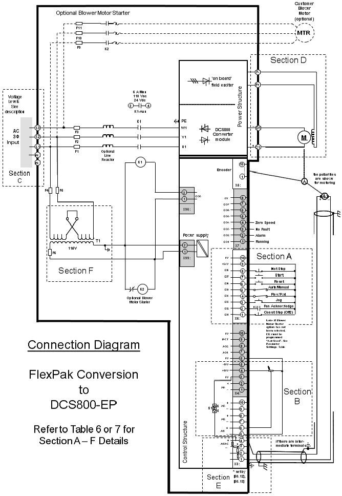
Wire and configure the drive as shown in table 6 below and the accompanying diagram. The table references a section of the diagram to make it easier to locate the connections
| Drawing Section | Function | Typical Reliance Terminal | Recommended DCS800-EP Terminal | DCS800-EP Parameter(s) to change* |
| Power | ||||
| C | AC Mains – L1 | 81, 181 | L1 | Use commissioning assistant to program the appropriate armature and field parameters |
| AC Mains – L2 | 82, 182 | L2 | ||
| AC Mains – L3 | 83, 183 | L3 | ||
| D | DC Motor Armature + | A1 | (C1) | Use proper procedures to determine correct polarity of armature, field and tachometer |
| DC Motor Armature – | 45 | (D1) | ||
| DC Motor Field + | F1 | (F+) | ||
| DC Motor Field – | F2 | (F-) | ||
| E | Tachometer + | 21 | X3:1,2 or 3* | *Depends on tach voltage. See Hardware Manual section “SDCS-CON-4 board” or Quick Guide. |
| Tachometer – | 22 | X3:4 | ||
| Tachometer Shield | 23 | |||
| F | Control Transformer | Verify DCS800-EP matches the AC input voltage. See “Alternate Line Voltage” Section of the DCS800 Installation and Start Up manual. | ||
| Digital Control | ||||
| A | +24V | 1,7,11,14 | X6:9 | None |
| 3-wire control | ||||
| Start (Run) | 2 | X6:7 DI7) | Set 10.15 to “DI7DI8” | |
| Not Stop | 3 | X6:8 (DI8) | Set 10.16 to “DI7DI8” | |
| 2-wire control | ABB function only | |||
| On / Off | NA | X6:7 (DI7) | 10.15 = “DI7” (default) | |
| Run / Stop | 2, 3 | X6:8 (DI8) | 10.16 = “DI8” (default) | |
| Jog1 | 4 | X6:3 (DI3) | Set 10.17 to “DI3” | |
| All | ||||
| Rev / Fwd2 | 5 | X6:4 (DI4) | Set 10.02 to “DI4” | |
| Auto / Manual | 6 | X6:5 (DI5) | Set 11.02 to “DI5” | |
| Coast Stop (Off2) | 8 or 9 or both in series | X6:1 (DI1) | Set 10.08 to “DI1” | |
| Reset | 10 | X6:6 (DI6) | 10.03 = “DI6” (default) | |
| Motor Fan Ackn | – – – | X6:2 (DI2) | 10.06 = “DI2” (default) | |
| Running Output | 27, 28 | X7:1 (DO1) | 14.01 = 801 14.02 = 2 | |
| Alarm Output | 29, 30 | X7:2 (DO2) | 14.03 = 801 14.04 = 7 | |
| No fault Output | 31, 32 | X7:3 (DO3) | 14.05 = – 801 14.06 = 3 | |
| Zero Speed | – – – | X7:4 (DO4) | 14.07 = 802 14.08 = 11 | |
| Analog Control | ||||
| B | Manual Speed Pot 0V | 18 | X3:5 and X4:6 | Set 11.06 to “AI1” |
| Manual Speed Pot +10V | 16 | X4:4 | ||
| Manual Speed Pot signal | 17 | X3:6 | ||
| Auto Speed 0V | 20 | X3:7 and X4:6 | Set 11.03 to “AI2” | |
| Auto Speed +10V | 16 | X4:4 | ||
| Auto Speed signal3 | 19 | X3:8 | ||
Table 6: Wiring and configuration chart (Rev. 3.6 and below)
- Jog only operates in 2-wire mode. (Firmware Version 3.7 allows it to also work in 3-wire mode.)
Note: “Customer Interlock” and “Coast Stop” both result in coast stopping the motor on the FlexPak 3000. Only one input (Coast Stop) is assigned on DCS800. See “incompatibility” section above for suggested remedy if more than one input is required. - Reverse operation requires the use of a regenerative drive (EP2 or FR)
- For both DCS800 and FlexPak 3000, can be voltage or current signal, selected by jumperNOTE: Motor thermostat requires RDIO-01 digital I/O extension board.
© Copyright 2016 ABB. All rights reserved.
Specifications subject to change without notice.
DCS800-EP | Reliance FlexPak 3000 Replacement
![]()
Wiring and Configuration
Firmware Version 3.7 and above (3-Wire Jog Macro)
A macro was introduced in firmware version 3.7 that automatically configures the DCS800-EP for FlexPak 3000 conversions.
The macro configures the drive as shown in table 7 and the accompanying diagram below. See “Application Macros” chapter of the DCS800 Firmware Manual for more information on macros.
| Drawing Section | Function | Typical Reliance Terminal | Recommended DCS800-EP Terminal | DCS800-EP Parameter(s) to change* |
| Power Connect the power cables as shown in table 6 above | To install the macro:
| |||
| +24 V | 1, 7, 11, 14 | X6:9 | ||
| Digital Inputs | ||||
| A | Start (Run) | 2 | X6:7 DI7) | |
| Not Stop | 3 | X6:8 (DI8) | ||
| Jog | 4 | X6:3 (DI3) | ||
| Rev / Fwd1 | 5 | X6:4 (DI4) | ||
| Auto / Manual | 6 | X6:5 (DI5) | ||
| Coast Stop (Off2) | 8 or 9 or both in series | X6:1 (DI1) | ||
| Reset | 10 | X6:6 (DI6) | ||
| Motor Fan Ackn | – – – | X6:2 (DI2) | ||
| Digital Outputs | ||||
| A | Running Output | 27, 28 | X7:1 (DO1) | |
| Alarm Output | 29, 30 | X7:2 (DO2) | ||
| No fault Output | 31, 32 | X7:3 (DO3) | ||
| Zero Speed | – – – | X7:4 (DO4) | ||
| Analog Inputs | ||||
| B | Manual Speed Pot 0V | 18 | X3:5 and X4:6 | |
| Manual Speed Pot +10V | 16 | X4:4 | ||
| Manual Speed Pot signal | 17 | X3:6 | ||
| Auto Speed 0V | 20 | X3:7 and X4:6 | ||
| Auto Speed +10V | 16 | X4:4 | ||
| Auto Speed signal2 | 19 | X3:8 | ||
Table 7: Wiring and configuration chart (Rev. 3.7 and above)
- Reverse operation requires the use of a regenerative drive (EP2 or FR)
- For both DCS800 and FlexPak 3000, can be voltage or current signal, selected by jumper
* Also see next section
NOTE: Motor thermostat requires RDIO-01 digital I/O extension board.
© Copyright 2016 ABB. All rights reserved.
Specifications subject to change without notice.
DCS800-EP | Reliance FlexPak 3000 Replacement
![]()