Adjustable Speed Drives –
(a.k.a. Variable Speed Drives)
What They Are, How They Work
Application Information
- Adjustable Speed Drives – Application Information
- DC Drives – Principles of Operation
- DC Drive Types
- DC Motor Control Characteristics
- AC Drives – Principles of Operation
- AC Controller Types
- AC Motor Control Characteristics
- Motor Selection
- AC vs. DC Drive Comparison
- Basic Mechanics
- Other Application Factors
- Measuring Machine Torque
- Mechanical Formulas
MOTOR SELECTION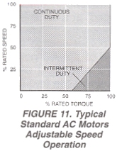
Constant Torque Applications – About 90% of all general industrial machines, other than fans and pumps, are constant torque systems where the machine’s torque requirement is independent of its speed.
- Standard three-phase AC motors, designed for fixed speed operation at standard line frequency, may be easily adapted for use with the AC controller by considering the following:
- A slight increase in motor losses occurs with inverter power.
- The motor thermal capacity must typically be derated as a function of the minimum, continuous operating speed in accord with Figure 11, due to the reduced ventilation provided by the integral motor fan. Where the application requires 100% rated torque at speeds below 50% of synchronous speed, a separately powered ventilation blower, a nonventilated motor with greater reserve 100 thermal capacity or, a motor with higher rated capacity should be used. When a separately powered ventilation blower is used, a thermostat should be built into the motor to prevent damage which may result from a failure in the ventilation system.
- Any three-phase synchronous or induction AC motor designed expressly for adjustable speed service by inverter control may normally be used over its design speed range with the AC controller.


Variable Torque Applications – The application of standard AC motors to adjustable speed variable torque applications such as centrifugal fans or pumps is ideal from a motor cooling standpoint. The torque characteristics of a variable torque (cubed exponential horsepower) load are such that the load falls off
rapidly as the motor speed is reduced. 100 The variable torque load eliminates the necessity to derate the motor due to excessive heat resulting from diminished motor cooling at reduced speeds. Figure 12 illustrates the relationship between speed and torque in variable torque applications.
Potential Power Savings – Most fan and pump applications require the system to run for sustained periods at reduced outputs by either reducing the speed of the motor or by mechanically alter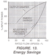 ing the flow. Figure 13 illustrates typical energy savings, in percent of rated power, which can be realized when using an adjustable frequency controller to reduce motor speed and thereby system flow as opposed to a constant speed motor
which has its system flow varied by an outlet damper.
Constant Torque Operation – The ability of the AC controller to maintain a constant’ 20 volts/Hz relationship is ideal from a motor standpoint. This permits operation of the motor at rated torque from near standstill to rated speed.
Figure 14 represents the relationship between torque, horsepower and motor speed with a maintained volts/Hz ratio using a 60 Hz controller for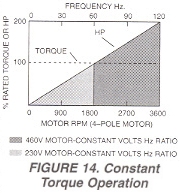 illustration. A standard 4-pole 460V motor can be controlled by this method to its synchronous speed of 1800 RPM. If the same motor were wound for 50% of the input voltage (230V), it could be controlled with constant torque to double the normal rated speed and horsepower. The motor would not be “overvoltaged” because the volts/Hz ratio could be maintained e.g.: a motor wound for 230 VAC can supply constant torque to twice the AC line frequency when used on a 460V power source without overvoltaging the motor because the volts/Hz ratio of 230V/60 Hz is the same as 460V/120 Hz. The horsepower would also double since the same torque would be developed at twice the normal rated speed.
Caution must be observed when applying standard motors for continuous low speed, rated torque operation. The motor’s self-cooling capability is dependent upon self-ventilation schemes with efficiency that is considerably reduced at lower operating speeds.
Constant Horsepower Operation – AC motor controllers are also adaptable to constant horsepower operation as shown by Figure 15. With this mode of operation, the volts/Hz ratio is maintained to a specific frequency, normally 50 or 60 Hz. At this point, the voltage is “clamp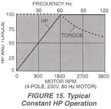 ed” at a constant level while the frequency is adjusted further to achieve the desired maximum speed. Since the controller maximum output voltage is limited to the voltage of the AC power source, the volts/Hz ratio must decrease beyond this point as the frequency increases. The motor becomes “voltage starved” above the clamping point and torque decreases as speed increases, resulting in constant horsepower output.
As shown in Figure 15 the drive provides conventional constant torque/variable horsepower operation up to 60 Hz which is equivalent to the 1800 RPM base speed of the 60 Hz motor. Between 1800 and 3600 RPM, the drive provides constant horsepower/variable torque operation. If constant horsepower is required between 900 and 3600 RPM (a 4:1 speed range) – using the same 1800 RPM base speed motor, the drive rated horsepower must be increased since 900 RPM intersects the curve at a point which is 50% of rated horsepower.
Constant HP operation (above synchronous speed) is limited to induction motors only. In addition, at some point, typically around three times base speed for a four-pole induction motor, the breakdown torque of the motor prevents further constant horsepower operation. Synchronous reluctance motor characteristics prevent operation in this mode.
Multiple Motor Operation (From a Common Controller) – An adjustable frequency AC motor controller is ideally suited for simultaneous control of multiple motors in process line applications. All motors are operated at a common frequency and are therefore synchronized at a common speed. Tracking accuracy between the individual motors varies only by the difference in their loads, typically 0.5% to 3% with standard NEMA Design B motors and 0.0% with synchronous reluctance types.
Where tracking ratios other than 1:1 are desirable, gear boxes, fixed or adjustable sheaves may be used to attain the desired individual speeds. Two-pole, four-pole and six-pole motors may also be mixed to obtain various individual motor operating speeds when operated from a common adjustable frequency controller. Selection of a properly rated controller should be made with consideration for the total KVA required by all the motors which are normally started and stopped simultaneously. Some process line applications require the ability to selectively start and stop one or more of the motors while the others are operated at the desired speed. A standard motor started under this condition instantaneously draws locked-rotor current of 600-800%.
Unless this factor is considered in the selection of an adequately rated controller, the additional load may exceed the capacity of the power unit, reducing the voltage to the entire system which could cause the line to stall or trip off.
Adjustable Speed Drive Application Information provided by: FINCOR Automation