![]()
Soft Switching Technology
APPLICATION NOTES
FINCOR ELECTRONICS ADJUSTABLE SPEED DRIVES 5700 & 6600
SOFT SWITCHING TECHNOLOGY
Introduction
Technology to control the speed of AC motor continues to develop at a fast pace. Adjustable frequency drives (AFDs) are a significant part of this development. Energy savings, less wear on the mechanical components, and better process control are the primary factors which push the rapid advancement of this technology.
Today’s AFD technology with a pulse width modulation (PWM) microprocessor based algorithm, uses insulated gate bipolar transistor (IGBT) to generate the variable voltage and frequency required to control the speed of AC motor. Since IGBT devices can switch at high carrier frequencies (up to 15Khz), there are several advantages:
- More low speed torque for applications where nominal motor torque is required close to zero speed.
- Quieter motor operation which reduces audible noise
- Improved low speed stability which minimizes low speed oscillations.
Unfortunately, fast switching IGBT technology also generates a very fast voltage rise (dv/dt) in the output waveform which induces additional stress on the motor insulation.
Pulse Width Modulation

Sine Wave Generated by Utility
Sine Wave Generated by Utility
AC is represented by a sine wave where the period of the wave is the inverse of its frequency and the height is equal to its magnitude When AC motors are connected directly to the utility line (across the line), they operate at a fixed speed. The input voltage could be 230 or 460 volts at 60 hertz in the USA and 380 volts at 50 hertz in other parts of the world. With sinewave at this low of a frequency, the motor and the cable see a peak voltage that is the RMS voltage times 1.414, or about 650V for a nominal 460V line. Allowing for high line transients, a 1000v insulation dielectric rating on the motor is usually adequate.
Pulse Width Modulation
Pulse width modulation, usually referred to a “PWM,” is a type of AFD technology that achieves frequency and voltage control with a drive section called the inverter. By using PWM technology, a constant dc bus voltage is chopped into voltage pulses of fixed amplitude and variable width to approximate a sine wave output to the AC motor (as represented by the sine wave on the PWM graph).
Voltage Rate of Rise (dv/dt) Issue
The rapid rise of voltage associated with PWM chopping combined with impedance differences between the cables and the motor, acts like a transmission line causing voltage reflection. As the pulse reflect, they reinforce each other causing peak voltage on the cable and at the motor terminals which can be several times the nominal drive output voltage.

Voltage Rate of Rise (dv/dt) Issue

Bipolar transistor drives also have high internal losses and low efficiency.
Early AFD’s avoided pulse reflections by using bipolar transistor to chop the DC bus voltage and create the required output frequency. This technology has the advantages of low dv/dt, but also low switching frequency which causes the performance issues described in the first section. Bipolar transistor drives also have high internal losses and low efficiency.
AFD’s overcame the limitations of bipolar transistors with the development of IGBT’s. The newer switching devices had the capacity to turn “on” and “off” much faster than their predecessors and yielded increase performance and efficiency. IGBTs were quickly adopted because of these advantages, and most low voltage AFD’s use this technology today.
 However, the faster switching times and higher dv/dt of the IGBT’s caused peak voltage at the motor terminals to approach 2 times the peak voltage. This forced the use of special motor’s and also required special attention during installation. Inverter duty motors are commonly specified to insure that the insulation dielectric rating is suitable, which in most cases is above 1600V.

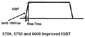
5700, 5750 and 6600 AFD’s products utilize improved fourth generation IGBT devices and soft-switching gate control circuits.
5700, 5750 and 6600 AFD’s products utilize improved fourth generation IGBT devices and soft-switching gate control circuits. This improves dv/dt by approximately 50%, which in turn reduces the motor peak terminal voltage. The newly developed IGBT’s have reduced internal losses, while the gate circuitry has been redesigned to provide lower dv/dt without compromising performance. This reduces motor insulation dielectric strength minimum rating requirements, allowing 1000V insulation dielectric strength motor to be applied with these drives in many applications.
reduction in the peak voltage at the motor terminals
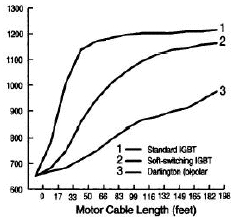
The graph at the right shows the reduction in the peak voltage at the motor terminals in relation to the cable length between the motor and drive for the 5700, 5750 and 6600 and standard IGBT drives without soft-switching.
Fincor Electronics 5700, 5750 and 6600 product family enhances motor performance and greatly reduces voltage stress on the insulation of the driven motor.

compares peak voltages between a 5700, 5750 and 6600 drives with soft switching technology and a traditional drive
The graph at the right compares peak voltages between a 5700, 5750 and 6600 drives with soft switching technology and a traditional drive that does not have this technology.
1 = Traditional Drive (no soft-switching)
2 = Fincor 5700, 5750, & 6600 (soft-switching)
Benefits of Soft Switching Technology |
|
| Feature | Benefit |
| Reduced motor insulation stress | Increased motor life |
| Use of 1000V insulation motors where application conditions permit | Reduced AC motor cost |
| Increase drive/motor cable run distance before consideration of output filters | Reduced installation cost Reduced installation time Reduced panel/wall space |
In addition to the above benefits, the 5700, 5750 and 6600 series ac drives provide the following:
- Dynamic torque vector control smooth, precise, and efficient motor operation.
- Keypad that functions as a copy unit.
- Built-in RS-485/Modbus RTU for easy connection to process controllers.
- Compact size: side by side installation with zero clearance in ratings of 30Hp or less.