PLEASE NOTE: Effective 2019, we no longer supply Control Techniques variable frequency drives and components. We have drives from several other manufacturers which can meet or exceed the performance characteristics of the Control Techniques line. Simply complete the form below, or contact us with the model of your current or obsolete Control Techniques drive and we’ll be glad to identify a suitable replacement.
Also, the Fincor and Saftronics lines of AC variable frequency drives, DC variable speed drives, and reduced voltage starters were once owned by Emerson but have been obsolete for several years. However, we have many years’ experience working with these drives and can quickly identify replacements capable of exceeding the quality and performance of these older drive technologies. For a suitable replacement, fill out the form below or contact us with your drive or application requirements, and we’ll handle it from there!
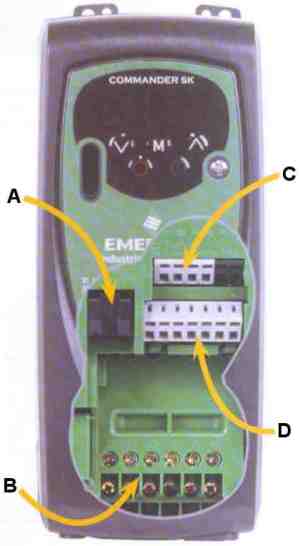
Commander SK | |
Simplicity with Function |
- Overview
- Features & Prices
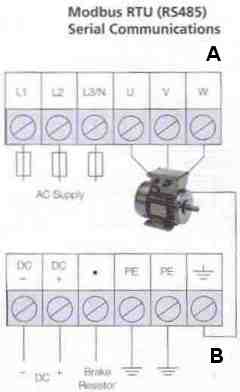
- Terminal Diagram and Description
- Specifications and Dimensions
- Options
- Operator Interface
- Power Accessories
- Environmental Protection and Cable Management
- Input / Output
- Communication
- Programming Software
TERMINAL DIAGRAM
 | 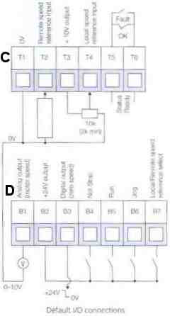 |
TERMINAL DESCRIPTION
| Pin | Type/Description | Default Function | Notes |
| T1 | 0V Common | Common for External Analog Signals | |
| T2 * | Analog Input 1 (A1) either voltage or current | Remote speed reference input 4-20mA | |
| T3 | +10VDC | Reference Supply | 5 mA max Short Circuit Protected |
| T4 | Analog Input 2 (A2) or Digital Input | Local Speed reference input 0-10V | 0 to +10 VDC (AI) 0 to +24 VDC (DI) Sample Times 6ms |
| T5 T6 | Status Relay (Normally open) | Drive Healthy | 240 VAC 30 VDC 2A/6A resistance |
| B1 | Analog Output 1 single ended Unipolar | Notor speed | 0 to +10 VDC @ 5 mA max Update Time 6ms |
| B2 | +24 VDC Output | User Supply | 100 mA max |
| B3 | Digital Input/Output Pulse Output | Zero speed | 0 to 24 VDC, 6.8k Ohms input Update Time 1.5ms Pulse output to 10 kHz |
| B4 | Digital Input | Not-stop | 0 to 24 VDC, 6.8k Ohms Update Time 1.5ms |
| B5 | Digital Input | Run | 0 to 24 VDC, 6.8k Ohms Update Time 1.5ms |
| B6 | Digital Input | Jog | 0 to 24 VDC, 6.8k Ohms Update Time 1.5ms |
| B7 | Digital Input / Pulse Input | Local/Remote Speed Reference Select A1/A2 | 0 to 24 VDC, 6.8k Ohms Update Time 1.5ms Pulse output to 50 kHz |
| Programmable Analog All Analog I/O is scalable | Programmable Digital |
* 4-20, 20-4, 20-0mA are also available. See Commander SK Getting Started Guide.
Information provided by Control Techniques, a world leader in the design, production and marketing of electronic drives for the control of electric motors.